This code will display name (Google in this case) on LCD. You can change the name in code, its up to you how can you modify this programe.
org 0h
lcall Initialization
lcall clear
mov a,#'H'
lcall dat
mov a,#'I'
lcall dat
mov a,#8ah
lcall command
mov a,#'G'
lcall dat
mov a,#'o'
lcall dat
mov a,#'o'
lcall dat
mov a,#'g'
lcall dat
mov a,#'l'
lcall dat
mov a,#'e'
lcall dat
agains: sjmp agains
initialization:
mov A, #38H ; Initialize, 2-lines, 5X7 matrix.
lcall Command
mov A, #0EH ; LCD on, cursor on
lcall Command
mov A, #01H ; Clear LCD Screen
lcall Command
mov A, #06H ; Shift cursor right
lcall Command
ready:
setb P1.7 ;D7 as input
clr P2.1 ;RS=0 cmd
setb P2.0 ;RW=1 for read
again:
setb P2.2 ;H->L pulse on E
clr P2.2
jb P1.7, again
ret
dat:
mov P1, a ;move acc. dat to port
setb P2.1 ;RS=1 dat
clr P2.0 ;RW=0 for write
setb P2.2 ;H->L pulse on E
clr P2.2
lcall ready
ret
command:
mov P1, A ;move acc. dat to port
clr P2.1 ;RS=0 for cmd
clr P2.0 ;RW=0 for write
setb P2.2 ;H->L pulse on E
clr P2.2
lcall ready
ret
clear:
setb P2.2 ;enable EN
clr P2.1 ;RS=0 for cmd.
mov a,#01h
clr P2.2 ;disable EN
lcall ready
ret
lcall initialization
lcall clear
mov A,#'H'
acall dat
mov A,#'I'
lcall dat
end
Friday, July 9, 2010
Thursday, July 8, 2010
8051 Assembly Code for Stop Watch and Counting Modes
This code do multi-operations by selecting its modes. For more detail look at the following table.

Following is the Assembly Code in text file. Save it and enjoy...
Click here to download

Following is the Assembly Code in text file. Save it and enjoy...
Click here to download
8051 Assembly Code for Left & Right Shift with Counting
This code do left and right shifting on port P0 and P2 from up to down or down to up depends on the mode. It also generate 8-bit count on p0 and 8-bit on p2 pins of 8051
Follwing is the Code in text file just download it and enjoy..
Click here to download.
Follwing is the Code in text file just download it and enjoy..
Click here to download.
220v AC to 12v DC Supply without using of transformer
In this mini supply we don't use the transformer to step down voltages. It gives few mA and generate less heat. It is low cost project with less component use.The main circuit diagram is shown below.

PCB design is as following.

PCB layout with silk is shown below.

3D view of this circuit is shown. in this we us bridge rectifier of 5Amps.


PCB layout with silk is shown below.

3D view of this circuit is shown. in this we us bridge rectifier of 5Amps.

8051 Generic Board
This board is the key tool to visualize your microcontroller output. It is so simple and easy to build.
In this project we use seven segment to visualize the microcontroller outputs of ports. By usning the cream shells we can interface any 8051 based project board.
Port 3 of 8051 in this generic board is bit accessible so that you can use these for multipurpose.
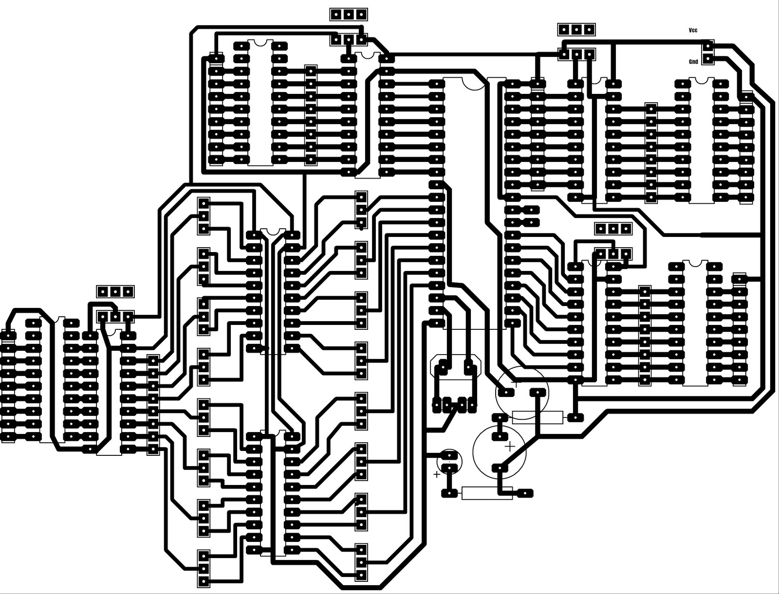
PCB layout of this board is shown below.
PCB layout with top silk is shown below for better understanding of component placement.
3D view of these components is shown.
In this view all 20 pin IC's are buffers 74LS245.
Resistor bank of 470(ohm) used with LED BAR.
To pullup port-0 of 8051 we use another resistor bank of 10k.

Tuesday, July 6, 2010
Build Stop Watch and Counter using 8051 Microcontroller
Main idea of this project is shown below:
8 bits on port p1is used to select the manual input.
p3.0, p3.1, p3.2 are used as selector lines.
To get the assembly code for this project click here
 Display Board Requirement Overview:
Four seven segment displays (SSD) are used for this purpose.

To Get the information about Microcontroller 89C51 interfacing board click here.
This Project has different modes of operation

The PCB design of 8051 Generic Board is shown below.
To get the information about etching process click here.

PCB design with top silk is shown below.

3D view of components are as following.

8 bits on port p1is used to select the manual input.
p3.0, p3.1, p3.2 are used as selector lines.
To get the assembly code for this project click here

Four seven segment displays (SSD) are used for this purpose.

To Get the information about Microcontroller 89C51 interfacing board click here.
This Project has different modes of operation

The PCB design of 8051 Generic Board is shown below.
To get the information about etching process click here.

PCB design with top silk is shown below.

3D view of components are as following.

Subscribe to:
Comments (Atom)